Lab 9
Mapping
Uding the built 2D map of the static obstacle course set up in the lab, the robot is placed at several known positions, spun in a full 360° rotation while collecting ToF distance readings at fixed angular increments, and the resulting point cloud is converted into a line-based map for use in later localization and navigation labs. I chose the Orientation PID using the DMP method. This is because the ICM-20948’s on-chip DMP fuses accelerometer and gyroscope data internally and outputs a quaternion at a high and stable rate. Converting the quaternion to yaw gives a low-noise, low-drift angle reading which is better than integrating raw gyroscope values (refer to Lab 6 Orientation Control).
Scan
The robot performs the following sequence for each of 24 angular steps (15 deg each, 360 deg total, above the 14-step minimum required):
- For each step = 0 … 23:
- Set target = start_yaw + step x 15° (wrapped to [−180°, 180°])
- Run the orientation PID loop until:
- Is below 2 deg error and has been sustained for 300 ms OR until a certain amount passes
- Stop motors
- Take 5 ToF readings from each sensor and average them for noise reduction
- Store (yaw, avg_dist1, avg_dist2)
- Send data back to Python over BLE
- Post-prcoess (polar and cartesian/world coords)
Arduino
I added additional commands:
case START_SCAN:
    orient_idx = 0;
    run_scan();
    break;


case SEND_SCAN_DATA:
    for (int i = 0; i < scan_idx; i++) {
        tx_estring_value.clear();
        tx_estring_value.append(scan_yaw_arr[i]);
        tx_estring_value.append(",");
        tx_estring_value.append(scan_dist1_arr[i]);
        tx_estring_value.append(",");
        tx_estring_value.append(scan_dist2_arr[i]);
        tx_characteristic_string.writeValue(tx_estring_value.c_str());
        delay(10);
    }

    break;

case SET_SCAN_PARAMETERS:
    float num_steps_new, step_deg_new, settle_ms_new, timeout_new;
    robot_cmd.get_next_value(num_steps_new);
    robot_cmd.get_next_value(step_deg_new);
    robot_cmd.get_next_value(settle_ms_new);
    robot_cmd.get_next_value(timeout_new);
    NUM_SCAN_STEPS = num_steps_new;
    SCAN_STEP_DEG = step_deg_new;
    SCAN_SETTLE_MS = settle_ms_new;
    SCAN_PID_TIMEOUT = timeout_new;
    break;

case SEND_ORIENT_LOG:
    // (time, yaw, setpoint)
    for (int i = 0; i < orient_log_idx; i++) {
        tx_estring_value.clear();
        tx_estring_value.append(orient_log_time[i]);
        tx_estring_value.append(",");
        tx_estring_value.append(orient_log_yaw[i]);
        tx_estring_value.append(",");
        tx_estring_value.append(orient_log_sp[i]);
        tx_characteristic_string.writeValue(tx_estring_value.c_str());
        delay(5);
    }
    break;
The scanning was performed using:
void run_scan() {
    float start_yaw = yaw_dmp;   // capture starting orientation
    scan_idx = 0;

    for (int step = 0; step < NUM_SCAN_STEPS; step++) {
        float target = start_yaw + step * SCAN_STEP_DEG;

        // [-180, 180]
        while (target > 180.0f) target -= 360.0f;
        while (target < -180.0f) target += 360.0f;

        yaw_setpoint = target;
        orient_integral = 0;
        orient_prev_error = 0;
        orient_first_pid = true;
        orient_last_t = 0;
        orient_pid_running = true;

        unsigned long step_start = millis();
        unsigned long settled_since = 0;
        bool settled = false;

        while (millis() - step_start < SCAN_PID_TIMEOUT) {
            icm_20948_DMP_data_t dmp_data;
            myICM.readDMPdataFromFIFO(&dmp_data);
            if ((myICM.status == ICM_20948_Stat_Ok ||
                 myICM.status == ICM_20948_Stat_FIFOMoreDataAvail) &&
                (dmp_data.header & DMP_header_bitmap_Quat6)) {
                ... // logic here
                yaw_dmp = (float)(yaw_rad * 180.0 / M_PI);
            }

            run_orientation_pid_step();

            float err = yaw_dmp - target;
            while (err > 180.0f) err -= 360.0f;
            while (err < -180.0f) err += 360.0f;

            if (fabs(err) < 2.0f) {
                if (settled_since == 0) settled_since = millis();
                if (millis() - settled_since > SCAN_SETTLE_MS) {
                    settled = true;
                    break;
                }
            } else {
                settled_since = 0;
            }
        }

        stopMotors();
        orient_pid_running = false;
        delay(200);

        // average 5 ToF for stability
        float d1 = 0, d2 = 0;
        for (int r = 0; r < 5; r++) {
            while (!distanceSensor1.checkForDataReady()) { delay(1); }
            d1 += distanceSensor1.getDistance();

            distanceSensor1.clearInterrupt();

            while (!distanceSensor2.checkForDataReady()) { delay(1); }
            d2 += distanceSensor2.getDistance();
            distanceSensor2.clearInterrupt();
        }


        Serial.print(d1 / 5.0f);
        Serial.print(", ");
        Serial.println(d2 / 5.0f);

        scan_yaw_arr[scan_idx] = yaw_dmp;
        scan_dist1_arr[scan_idx] = d1 / 5.0f;
        scan_dist2_arr[scan_idx] = d2 / 5.0f;
        scan_idx++;
    }


    stopMotors();
    orient_pid_running = false;
}
Results
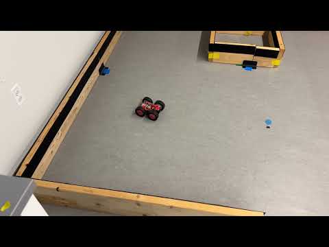
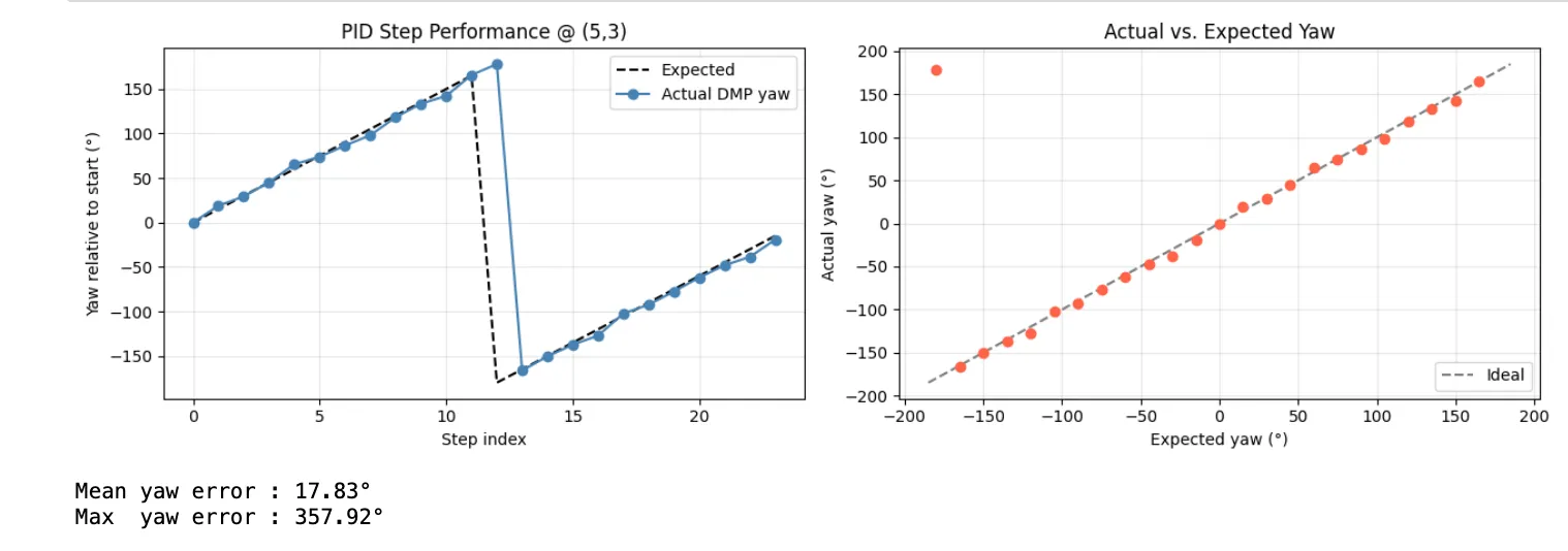
To verify repeatability, I ran multiple (3 times) scans at each location. The small deviations between runs confirm that the main source of error is sensor noise and mostly off-axis occurances. Other causes of error may be the environment itself, yaw drift, and me misplacing/misorientated the car during placement.
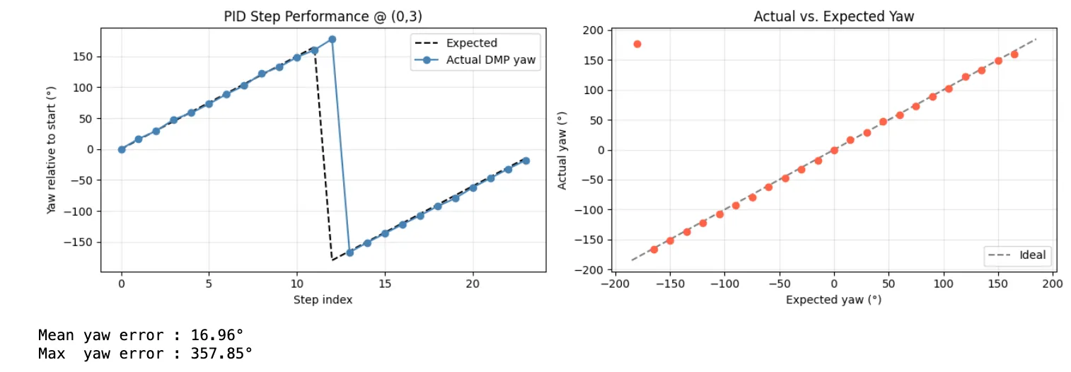
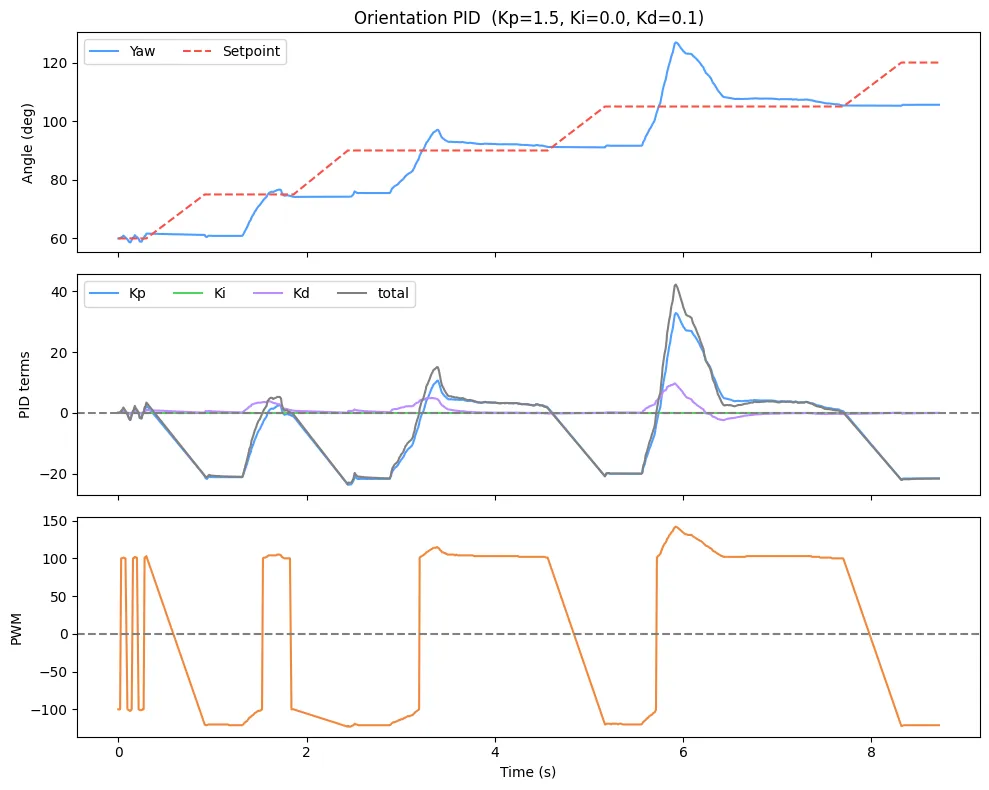
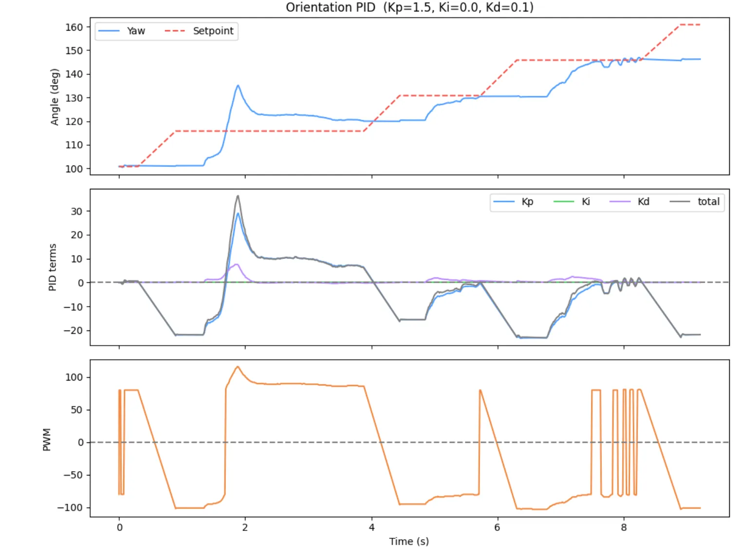
For each starting position, the graphs showing the yaw, PID terms, and PWM are below. I also included graphs to show that the behavior is as we want, where the left panel shows actual DMP yaw (blue dots) vs. the expected 15 degree increase (black dashed) over 24 steps. The right panel is a scatter of actual vs. expected, points cluster tightly on the diagonal, confirming the PID reaches each setpoint accurately.
(-3,-2)
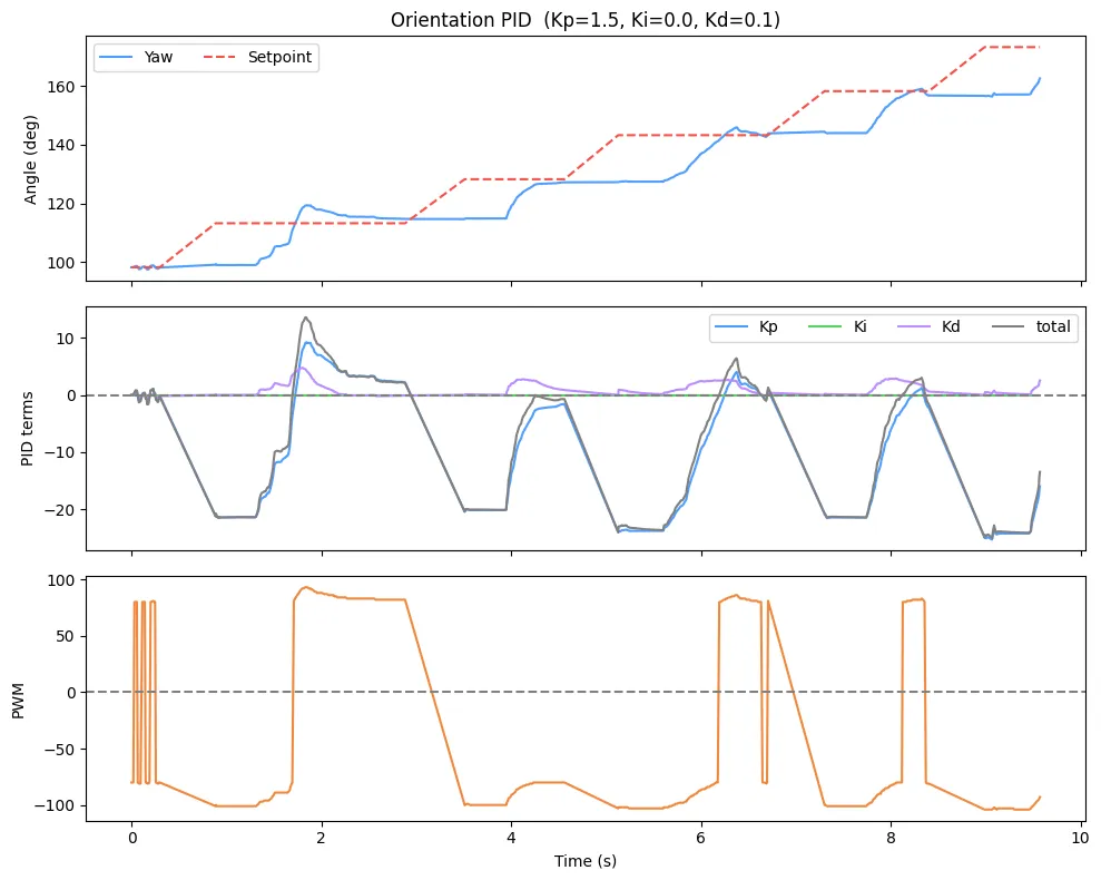
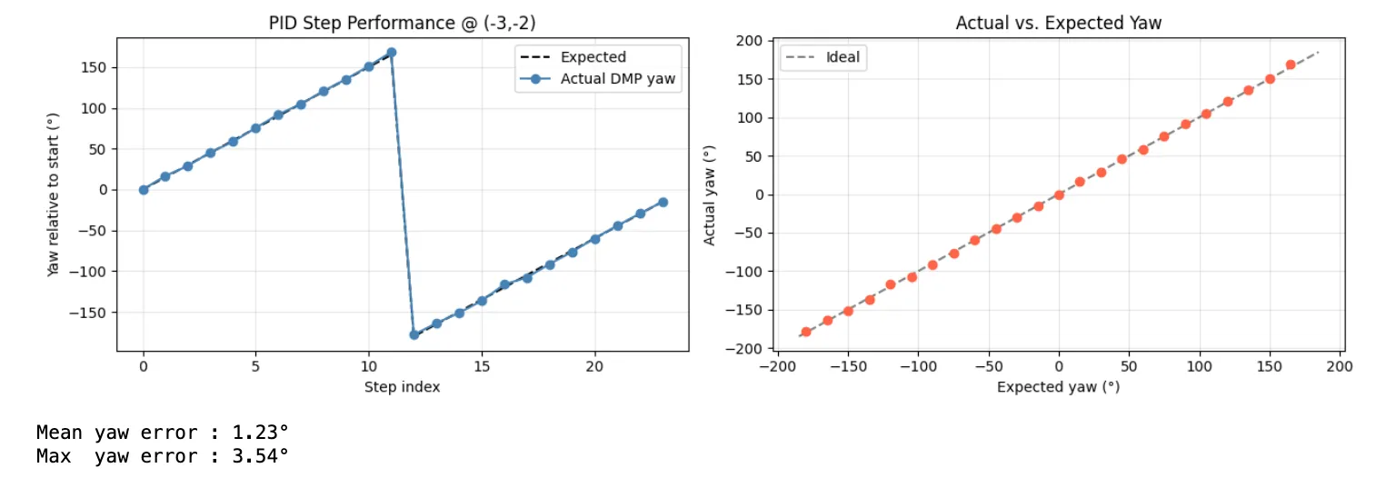
(0,3)
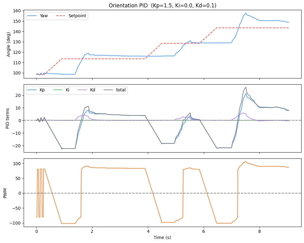
(5,3)
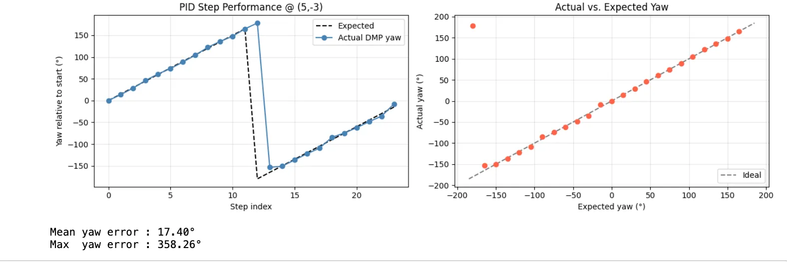
(5,-3)
If the robot is placed in the center of a 4mx4m empty square room, the distance to each wall is approx 2 m. With a worst-case 2 deg angular error (as determined in my code), the average and maximum positional error of my map from angular error is
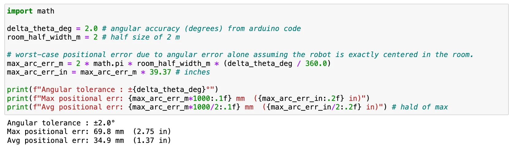
However, this does not account for off-axis rotation when my car doesn’t spin perfectly in place, ToF noise at long range readings, and DMP drift. As seen in the video, my off-axis rotation can introduce approx 5–10 cm of positional shift.
Scan Locations of Lab Map
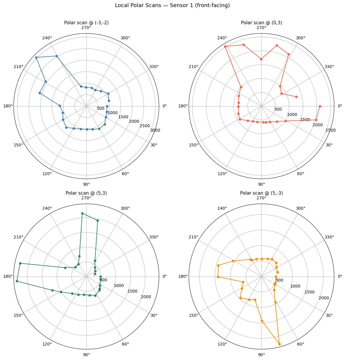
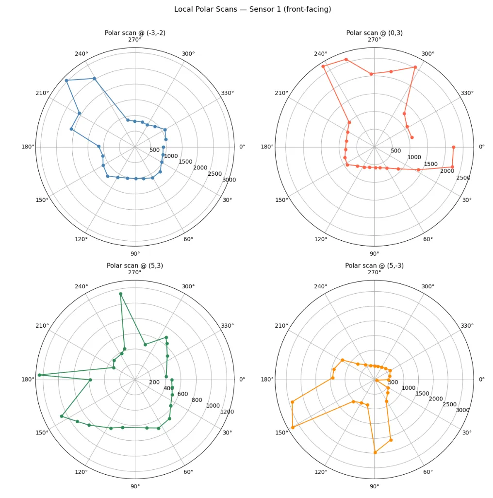
The robot was placed facing +y at each of the four required positions. The starting orientation was kept constant across all scans (scan positions (in feet)are (-3, -2), (0, 3), (5, 3), (5, -3)) to make post-processing consistent.
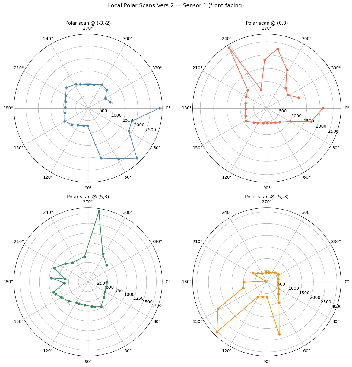
Polar Plots (Local Robot Frame)
Each polar plot shows ToF distance (in mm) vs. angle for the scan at that location, as seen from the robot’s own frame.
Transformation
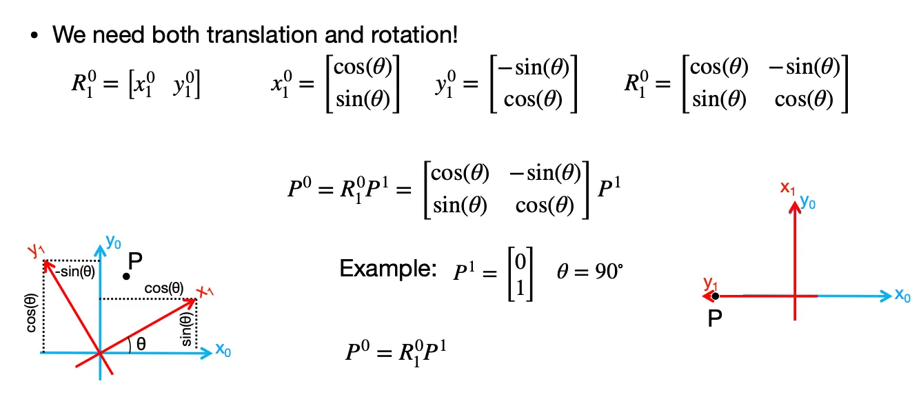
To merge all scans into one map, each point must be converted from the robot’s local polar frame to the global Cartesian world frame. Adjust the angles to account for the IMU’s clockwise convention and align them with the world coordinate system. That is, I had to add $\pi/2$ to align the sensor’s forward direction (car’s +x) with the world frame’s axes (where car forward faces +y in world), so that it points in the correct global direction. Add the sensor offset so distances are measured from the car’s center. Finally, translate each point by the robot’s position (x_robot, y_robot) to place it in the global world frame.
I referenced Lecture 2 on homogeneous transformation matrices. Note that in the picture, theta = −yaw_rel+ pi/2 for reasons mentioned above.
def scan_to_world(yaw_deg_list, dist_mm_list, robot_pos_ft,
                  sensor_offset_mm):
  yaws = np.array(yaw_deg_list)
  dists = np.array(dist_mm_list)

  yaw0 = yaws[0]
  yaw_rel = yaws - yaw0
  yaw_rel = ((yaw_rel + 180) % 360) - 180

  theta = np.deg2rad(-yaw_rel) + np.pi / 2

  d_ft = (dists + sensor_offset_mm) * MM_TO_FT

  x_world = robot_pos_ft[0] + d_ft * np.sin(theta)
  y_world = robot_pos_ft[1] + d_ft * np.cos(theta)

  return x_world, y_world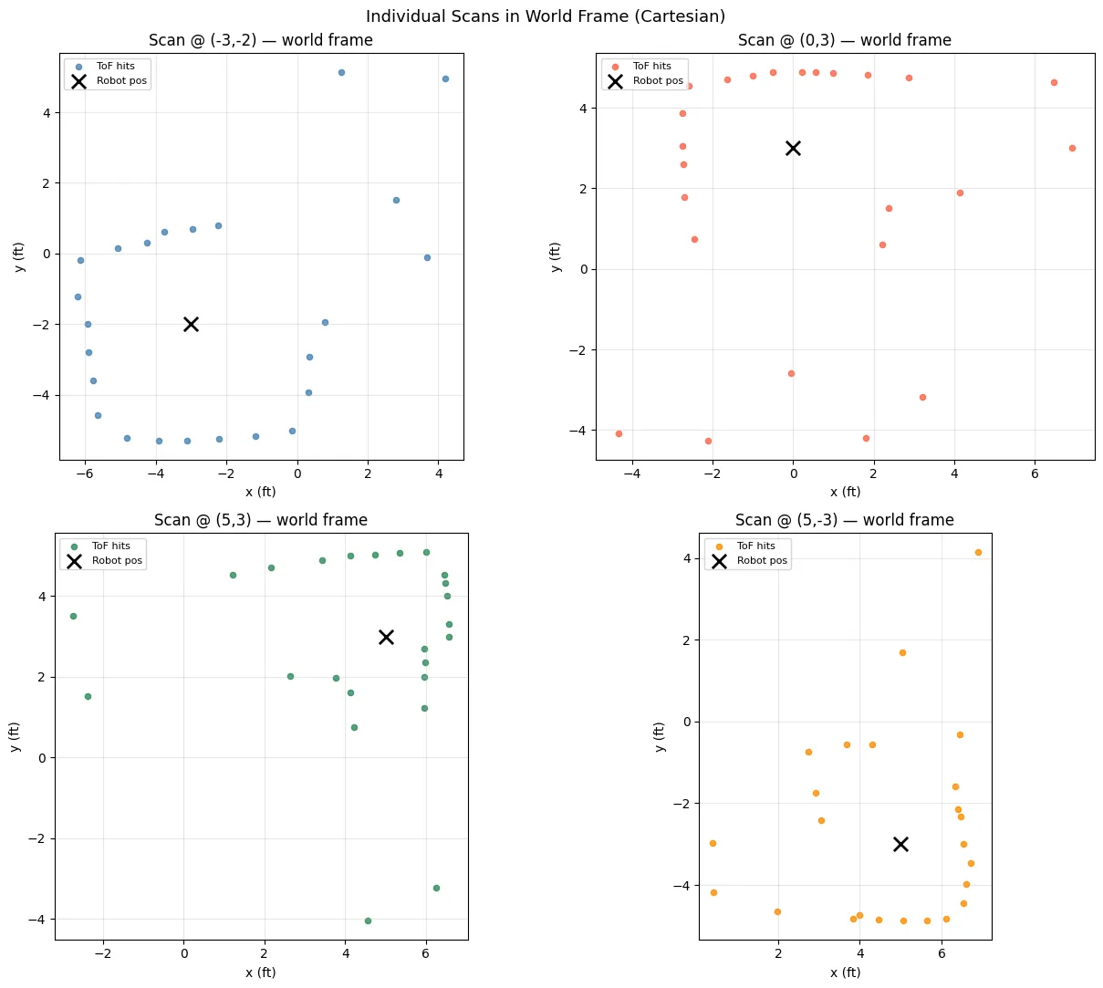
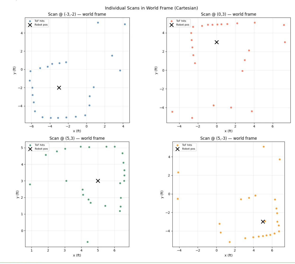
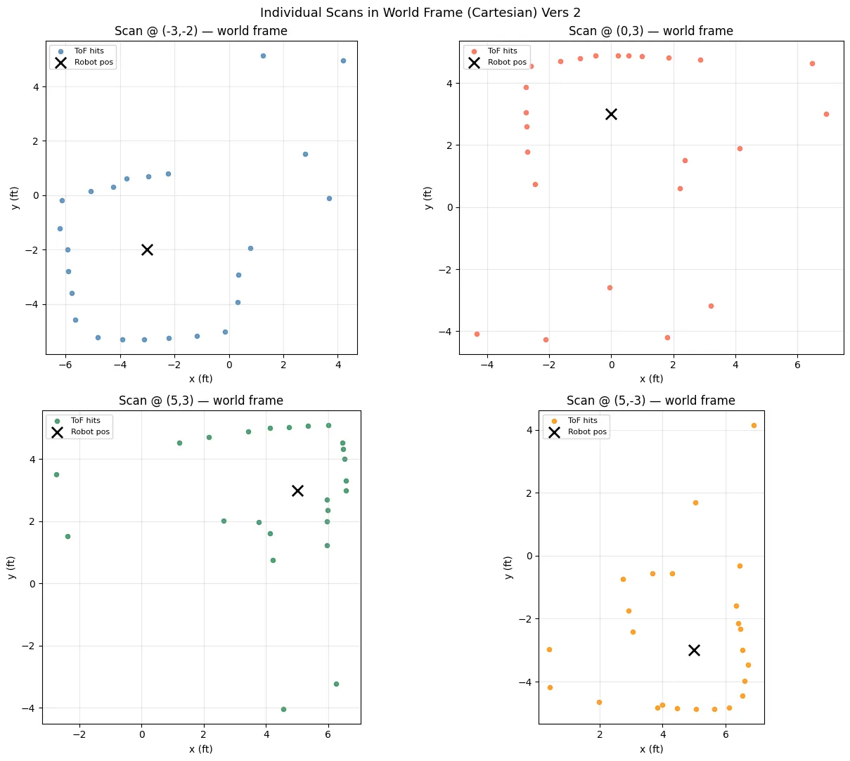
First Rendition of Maps
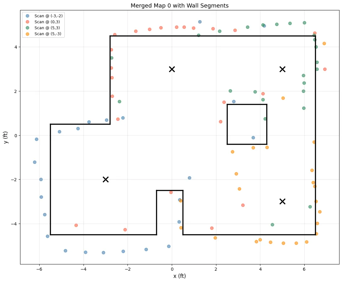
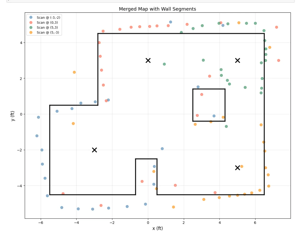
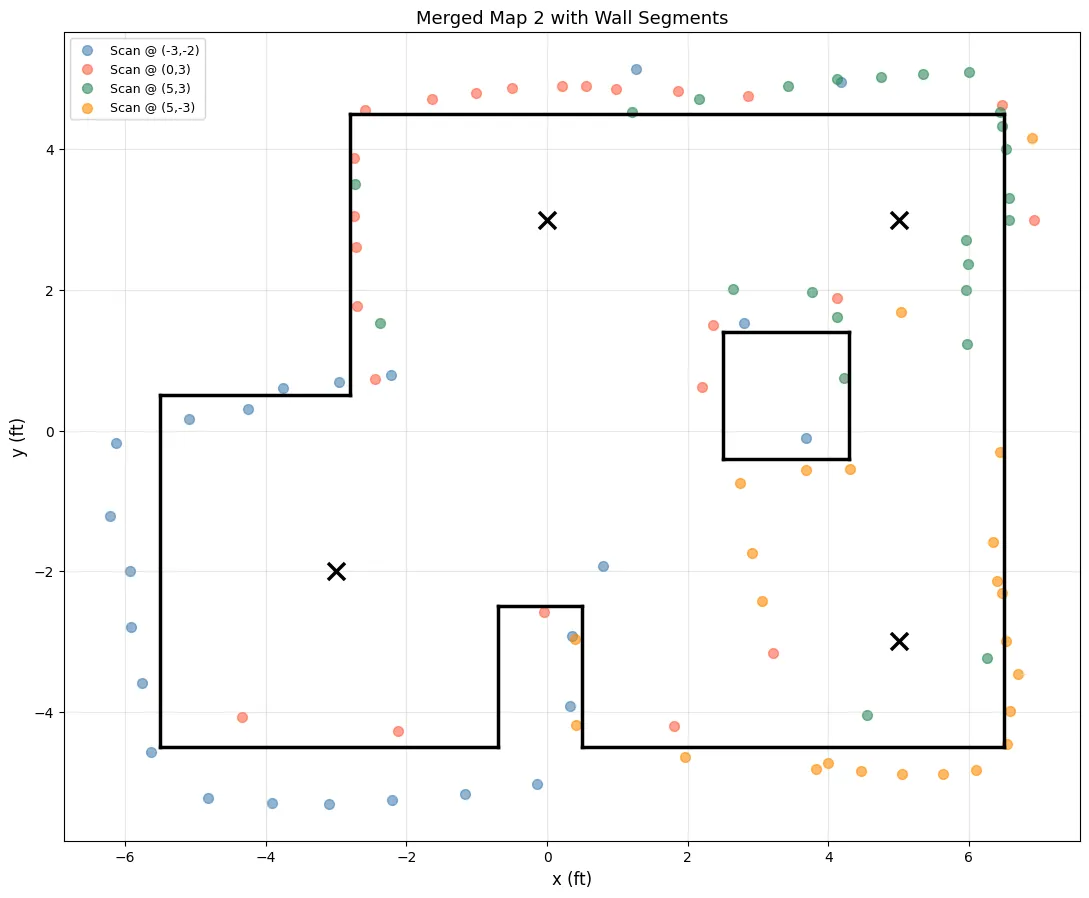
Additional Scans/Locations
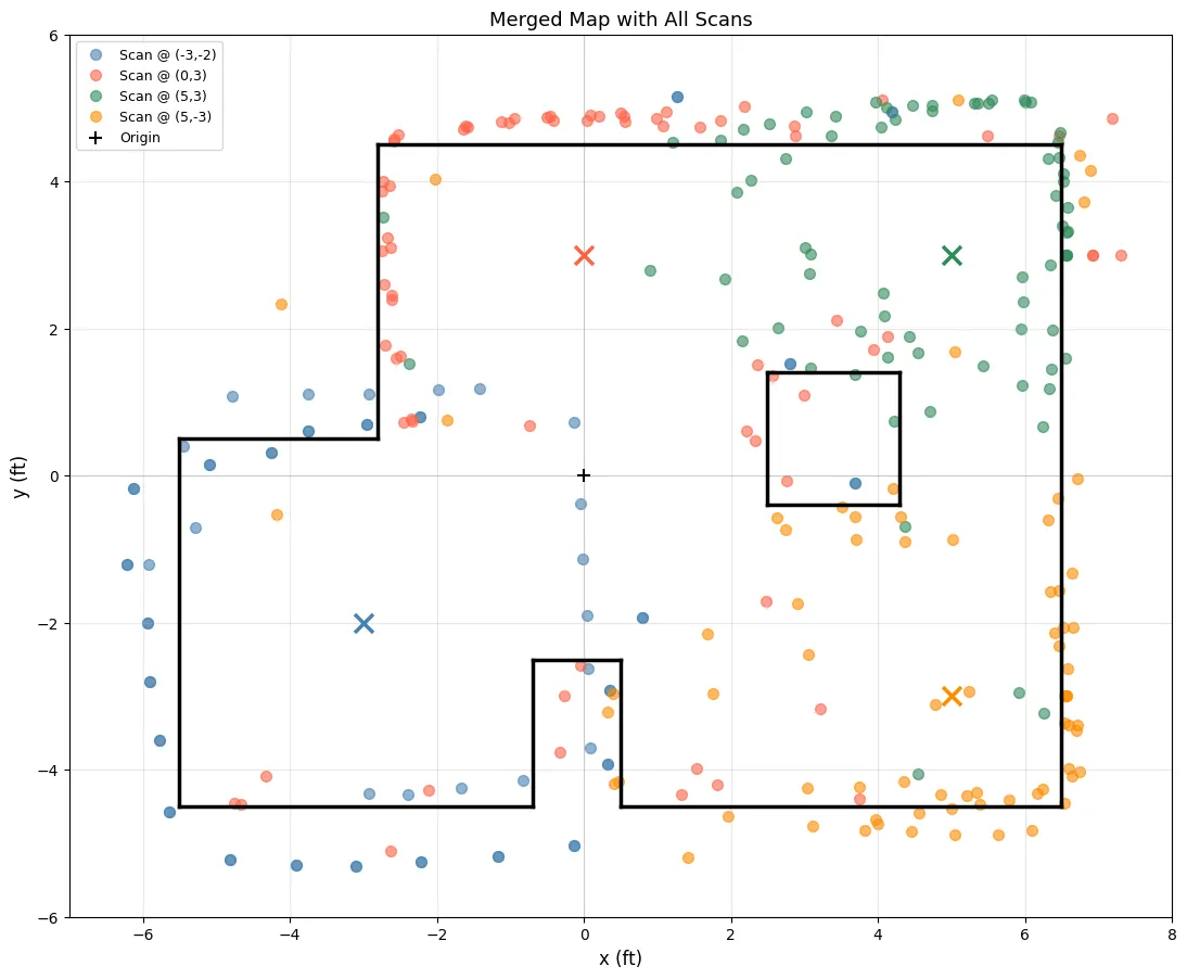
I compiled all scans into one map.
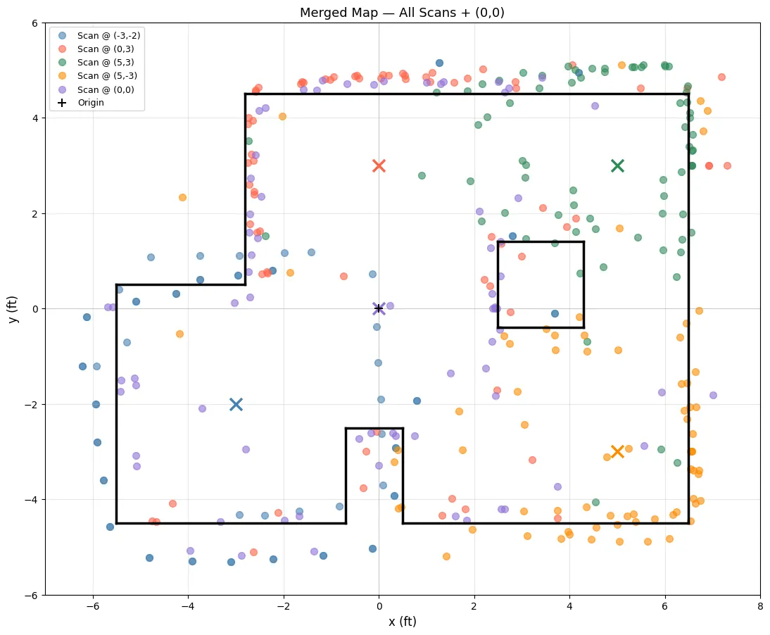
I then also used the additional marked locations (0,0) and to further verify the map.
Acknowledgements
I referenced Aidan McNay’s past lab report from from Spring 2025. I used ChatGPT to help me generate plots.